This is part 1 of a three-part series covering Minimum Detectable Activity (MDA) time constants. It covers linear ratemeters controlled by a conventional resistor-capacitor (RC) integration components.
Part 2: Determining MDA Time Constants - Logarithmic Ratemeters
Part 3: Determining MDA Time Constants - Microprocessor Controlled Ratemeters
The following information applies to the MDA equation (95% confidence) for linear analog ratemeter instruments, such as portable friskers and hand-held contamination monitors.
Many versions of MDA equations exist, but we recommend the use of the MDA equation referenced in our article “Detection Sensitivity – MDA and LLD”. It is written below in its original form (Equation A) for a timed count.
MDA - Equation A
where:
MDA = minimum detectable activity in dpm
Rb = background count rate in cpm
ts = sample counting time in minutes
tb = background counting time in minutes
E = detector efficiency in counts per disintegration
It is written again in modified form as Equation B, for the case in which we want the MDA to be in terms of a specific area, such as surface measurements in which we want the MDA in terms of dpm per 100 cm2. For this case, an additional factor is included in the denominator to adjust the MDA for the area of the detector being used.
Equation B also addresses the use of a ratemeter as the counting instruments, in which there is no clear sample and background counting time. It has been accepted that in ratemeter applications, twice the instrument's time constant can be substituted for the sample and background counting times. Thus, "2T" has been substituted for both "ts" and "tb" (sample and background counting time) in the original equation.
MDA - Equation B
(may be simplified algebraically, if desired)
where:
MDA = minimum detectable activity in dpm/100 cm2
Rb = background count rate in cpm
T = Time constant of counting instrument in minutes
E = detector efficiency in counts per disintegration
A = probe area in cm2
So, how does one determine the time constant ("T")? First, some definitions:
- Response Time: The time interval required for the instrument reading to change from 10% to 90% of the final reading (or vice versa) following a step change in the radiation field (i.e., signal) at the detector. [1]
*Note: All LMI specified response times are measured by injecting a fixed pulse rate from a pulse generator. - Time Constant: The time involved in the charging or discharging of an inductor or capacitor. One time constant is the length of time required to reach 63% of the full charge or discharge.
The specification related to time constant in the counter instruction manual is specified as response time — 10% to 90% of final reading. There are two methods of calculating the required "counter time constant" for the MDA as shown below in Method 1 and Method 2.
Method 1:
An approximate method used for conversion from the specified response time to the required time constant involves multiplying the response time data by 0.44.
Example: The Slow response position on a Ludlum Model 14C is specified at 22 seconds. Thus, 22 x 0.44 ≈ time constant of 9.7 seconds = 0.16 minutes for T.
Method 2:
The integration RC time constant can be calculated by multiplying R x C. There are 3 components associated with this calculation.
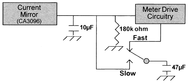
Example: The illustration shows the 3 components in a Model 14C circuit: 10µF, 180k ohm, and 47 µF. in the Fast response position, the RC time constant is 10 µF (10 x 10-6 F) x 180,000 ohms = 1.8 seconds or 0.03 minutes for T. For the Slow position, the 47 µF parallels with the 10 µF = 57 µF (57 x 10-6 F) x 180,000 ohms = 10.3 seconds or 0.17 minutes for T.
Locate the integration RC components by tracing the Fast/Slow response switch or current mirror to the components or by referring to the appropriate circuit board schematic located in the instrument's Instruction Manual.
References:
[1] American National Standard Performance Specifications for Health Physics Instrumentation - Portable Instrumentation For Use in Normal Environmental Conditions. New York: Institute of Electrical and Electronic Engineers; ANSI N42.17A-1989.
[2] Gollnick, D. A.; Basic Radiation Protection Technology, 4th Edition. Altadena, CA: Pacific Radiation Corporation; May, 2000.